I´m pretty proud of myself right now, because I could save my TS-651 mainboard after QNAP support stated this was impossible and a mainboard replacement was the only option left.
This HowTo document features the use of a Raspberry PI to do the actual BIOS flashing. If you are an electronics expert and have specific flashing hardware using SPI technology available you may use this instead.
I´ve really put some effort into this document in order to spare you guys the time I spend figuring this out and the money for unnecessary replacement hardware, but of course:
I take absolutely no responsibility for anything you do while following this guide!
Only do this, if your device is out of warranty and you are out of other recovery options!
Otherwise contact QNAP support and refer to the official BIOS recovery guide in the QNAP Wiki.
Prehistory - Why I had to do this:
During the firmware update from 4.3.3.0188 build 20170516 to 4.3.3.0210 build 20170606 the process exited with error code 999 - Execute Update Image Failed (see QNAP Wiki) . This was because of a broken DOM module, but I did not know at this point. Restart failed. Restart without HDD installed also failed (ex post: obviously). I thought, the data on the DOM was corrupted during firmware update and tried to fix this, as the NAS just went out of warranty a month before (as always...). Because I had no monitor attached to the NAS at this point, I did not recognize that the DOM was not even visible as a boot device in system BIOS.
I followed the QNAP Wiki: Firmware Recovery (x86) guide and attached keyboard and monitor to the NAS. As my BIOS displayed a fancy "splash screen" instead of the boot information that is quoted in the Recovery article, I again could not see, that the DOM wasn´t even recognized. After POST BIOS just stated that it could not find a device with a correct boot sector, which supported my theory of a corrupted DOM by firmware update.
I futher followed the guide and created a bootable USB stick with the Linux distribution "Damn Small Linux" (DSM). This did not completely boot up so I never saw the final screen of the guide. Instead there were a lot of "pc_keyb: controller jammed (0xFF)" errors on the screen. I tried to connect the keyboard to all available USB ports and restarted DSM each time; without success. Because I assumed a USB issue I entered BIOS and saw the option "Enable USB 3 support". Since I only had USB1 (keyboard) and USB2 (stick) devices attached, I disabled it. After a restart I was pretty annoyed, because this option did not do what it was stating ("Enabling/Disabling USB3 support"), but disabled USB on all ports alltogether!!
In (good) old times you could fix messed up BIOS settings by removing the CMOS battery and wait a bit, so it looses its memory and reverts to default settings. Unfortunately this new UEFI "innovation" obviously stores those settings persistently. As there was also no "Clear CMOS" header on the mainboard I was out of options and read in some forums about this issue. Result: I need to flash over the completely working BIOS anew to get back to default settings.
I found the QNAP Wiki article "How to flash BIOS if USB function is disable" (sic!) and contacted QNAP support for the BIOS file. As this request took about a week until I got a working download link I asked google for it. Third result is the Polish QNAP forum which hosts some of QNAPs BIOS images. I took it and flashed it. The flashing process completed with a success message. Unfortunately afterwards the device was completely dead. I really have no clue what happened, or why the BIOS file from the polish QNAP forum did not work. The ZIP archive had all accompanying documents from QNAP, the ROM had the correct size and was intended for the QW37 mainboard of QNAP. It was just a little outdated (QW37AR22 from 2014/05/19 instead of QW37AR32 from 2015/02/17).
Until now I digged myself and my NAS deeper and deeper into trouble. I did some research on the board and saw some serial (COM) connectors on it so I asked QNAP support explicitely whether there was any BIOS recovery option left using those or some other board connectors/jumpers/whatsoever. The answer of QNAP support was that there is NO WAY to recover the BIOS. I was advised to to order a replacement mainboard with a price quote of USD 250 + VA tax + shipping from their nederlands based warehouse. But still I had not completely given up on my board.
Now see how I digged myself out of the hole back to a completely working system without paying a single cent/penny (but admittedly a lot of time instead).
BIOS recovery
I stumbled upon a weird board connector called "JSPI1" next to the CMOS battery and the BIOS chip. As I found out, it is a mystery connector also featured on mainboards of MSI. As MSI officially only uses it for "internal purposes" they don´t mention it in their mainboard manuals, but the MSI community found out that it can be used to flash BIOSes on non-working (bricked) mainboards using SPI technology (Wikipedia (en): SPI, Wikipedia (de): SPI). I am just a business IT guy and not have no degree in electronic engineering, so I just understood the basics of the technology. But it was enough to be sure I can flash the BIOS chip using this board connector. I did some more research - mostly on the MSI customer forums. Some very bright members there shared their experiences building adapters (parallel port LPT1 to SPI) featuring electronic breadboards, resistors, capacitors and so forth.
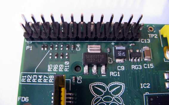
Since I had neither of it available, I thought my options through and remembered my old Raspberry PI 1 Model B lying around for years in my technical junk drawer. It features a GPIO header which I thought must be usable to do what a LPT port did for the MSI guys.
Aunt Google "Raspberry PI BIOS flash". First result is from a user called Pacman of the Win-Raid forums. I´ll refer to this post multiple times now. His HowTo post educated me on how this basically works, but I had to deviate from it multiple times:
What you need:
- Raspberry PI with GPIO pin header (at least the models 1 and 2 have it afaik)
- Raspbian OS (Debian for PI)
- Connector cable to connect pins individually (Cable Picture) or custom build one like in the Win-Raid forums post of Pacman
Software
When I bought my Raspberry PI, 1GB SD Cards were kind of standard, but nowadays this is awefully tight. If you have a larger card, you may follow Pacmans guide to install Raspbian Jessie, download the source of the application "Flashrom", install the Linux compiler packages and build it yourself. I did not have enough space on my SD card to even install the current "Lite" version of Raspbian Jessie (from here), so I installed the Minibian Jessie distribution by Luca Soltoggio (Sourceforge project site (Download)).
Unfortunately the Flashrom package for the armhf architecture of the Raspberry PI is only available on the repository of the new stable Debian version, called "stretch". Raspbian is officially currently still on its predecessor version "jessie", but has the stretch package respositories already available on their servers.
So I first brought the outdated Minibian installation up-to-date:
# apt-get update
# apt-get upgrade
Optional: # apt-get clean (deletes old package cache, I needed this space on my small SD card)
Afterwards I changed the repository configuration file /etc/apt/sources.list and simply replaced all "jessie" strings to "stretch"
# vi /etc/apt/sources.list
- Press [INSERT] key to enter insert mode. Navigate to the text places with cursor keys and replace "jessie" with "stretch".
- Press [ESC] to leave insert mode.
- Type :wq [ENTER] to save and exit the vi editor.
- Note: If the cursor keys don´t work right (making ^A, ^B characters): Exit the editor by typing :q! [ENTER] to exit vi without saving, enter it again and first thing type :nocp [ENTER] to disable the so called compatibility mode. Proceed with previous steps.
# apt-get upgrade
Optional: # apt-get clean
# apt-get dist-upgrade
All those commands take some time. Afterwards install the package "flashrom".
# apt-get install flashrom
On some former Raspbian distributions, the GPIO functionality was disabled in the linux kernel. Some old HowTo´s (including Pacman´s) advise to enable it in an outdated way: sudo vi /etc/modprobe.d/raspi-blacklist.conf and comment out the entry "blacklist spi-bcm2708" by adding a # in front.
In current Raspberry PI linux kernels this configuration has moved and changed (Source), so:
# vi /boot/config.txt
add to the bottom: dtparam=spi=on
save and exit vi editor. Reboot the Raspberry PI afterwards:
# reboot
Copy the BIOS image of your NAS to the Raspberry PI. I copied it using WinSCP and a SSH connection to the RPi into the folder /opt .
Now the software is ready to flash the BIOS of using the JSPI1 header on the mainboard.
Hardware
Now it is time to connect to cables.
! IMPORTANT ! The QNAP JSPI1 header is connected differently to the MSI JSPI1 header documented in the Win-Raid forum post by Pacman!
I read the specification document of the BIOS CHIP "Winbond 25Q64FWSIG" also called "W25Q64FWSIG" (PDF Document). On page 6 is the chip connection specification.
Note: Chip pin number is counted differently than connector pin numbers:
Chip pins:
______
| 1 | 8 |
| 2 | 7 |
| 3 | 6 |
| 4 | 5 |
----------
Pin 1 is marked with a silver circle on the chip.
Note: On my mainboard (QW37) the chip was mounted 90° turned with the connectors on top and bottom.
JSPI1 pins:
______
| 1 | 2 |
| 3 | 4 |
| 5 | 6 |
| 7 | 8 |
----------
Using a multimeter I measured which chip pin is connected to which JSPI1 pin on the board. Only 6 chip connectors are wired to the JSPI1 pins:
JSPI1 header pin assignment on the QNAP mainboard QW37 of TS x51
... and proably also x53
1 Voltage (VCC)
2 Ground (GND)
3 Chip Select (CS)
4 Clock (CLK)
5 Data Output (DO / MISO)
6 Data Input (DI / MOSI)
Source: own research
! WARNING ! The chip manual states that the operating voltage range of this BIOS Chip is 1.65-1.95V. If you want to play safe, you need to bring down the Raspberry PI´s output voltage of 3.3V or use a stabilized power source in the mentioned voltage range and connect it to JSPI1 pins 1 and 2.
The lowest voltage the Raspberry PI can supply is 3.3V (on pin 17). The following guide worked for me but it exposes the chip to an too high and therefore out-of-spec voltage. Do it on your own risk!
Raspberry PI GPIO pins we need:
| 2 | 4 | 6 | 8 | 10 | 12 | 14 | 16 | 18 | 20 | 22 | 24 | 26 |
| 1 | 3 | 5 | 7 | 9 | 11 | 13 | 15 | 17 | 19 | 21 | 23 | 25 |
17 Voltage (! 3.3V !) have not measured by multimeter, may be a bit lower when connected to the main board.
19 connect to JSPI1 Data Input (DI / MOSI)
21 connect to JSPI1 Data Output (DO / MISO)
23 Clock (CLK)
24 Chip Select (CS)
25 Ground (GND)
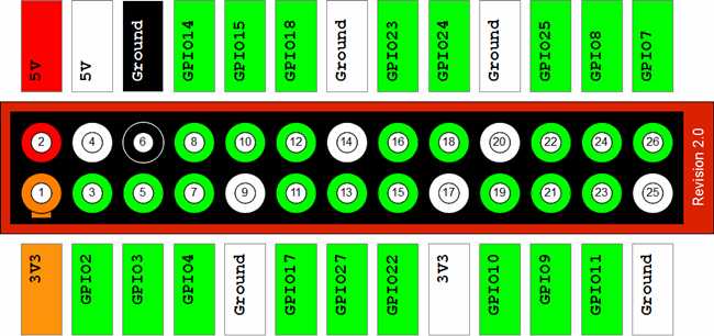
Source: Forum Post of Pacman on Win-Raid Forums
First I erased the chip to make sure, there are no traces of the non working BIOS left on it:
# flashrom -E -V -p linux_spi:dev=/dev/spidev0.0
This takes some minutes. Flashrom runs in verbose mode (-V option) and displays each memory address range it currently works on.
Afterwards I flashed the correct BIOS to the chip:
# flashrom -w /opt/QW37AR32.BIN -V -p linux_spi:dev=/dev/spidev0.0
This again takes some minutes and you can watch flashrom working again. If all went well it states:
Erase/Write done.
Verifying flash... VERIFIED.
Shutdown the Raspberry PI (or pull the plug) and disconnect the cables from the JSPI1 mainboard header.
If flashing went well, mount the mainboard back into the case and start it. BIOS should now come back, display starts, LEDs are blinking, etc.
Some Troubleshooting ideas if flashing doesn´t work right away:
If flashrom could not detect your BIOS chip even though it is listed on the Flashrom Compatibility List, you should try to:
- Do what I did and use a multimeter to measure which chip pin connects to which SPI header pin. Measure ohms. When it changes from indefinite towards 0 you have a connection.
- Double check the wiring
- Add capacitors to the wiring according to Pacman´s post on Win-Raid forums (and many other sources, just use Google "SPI BIOS flash" and look at the wiring they use)
Measure voltage while chip is connected and if it´s too low, increase it in very small steps (danger!)
We are done with flashing, but what about the broken DOM module? That was pretty easy in comparison.
See following post: [HowTo] Replace broken DOM module with a simple USB stick
Hope I could help somebody with this guide.
buggy82
Edit note: clarified description of Raspberry PI GPIO pins.